Ex Tools
Veraltet...
Dieses Programm wurde umbenannt in "Camera Commander: FLIR" und ist inzwischen fester bestandteil vom ThermoVision Programm.
#Einleitung
Dieses Programm ist entstanden, nachdem ich mir eine Wärmebildkamera FLIR E4 besorgt hab. Es wurde von DevTools abgeleitet.
Wie ich kurz zuvor erfahren hab, lässt sie sich softwareseitig erheblich verbessern und ist mit einem internen Kommunikationsanschluss ausgestattet.
Ziel ist es, eine Fernsteuerung für die Kamera zu bekommen, die möglichst weit das Potential der Kamera ausschöpft.
Dieses Programm steuert die Kamera über Telnet (USB Modus: RNDIS, RNDIS_MSD oder am besten RNDIS_UVC) oder über UART (benötigt eine Hardware Modifikation).
#Startoberfläche
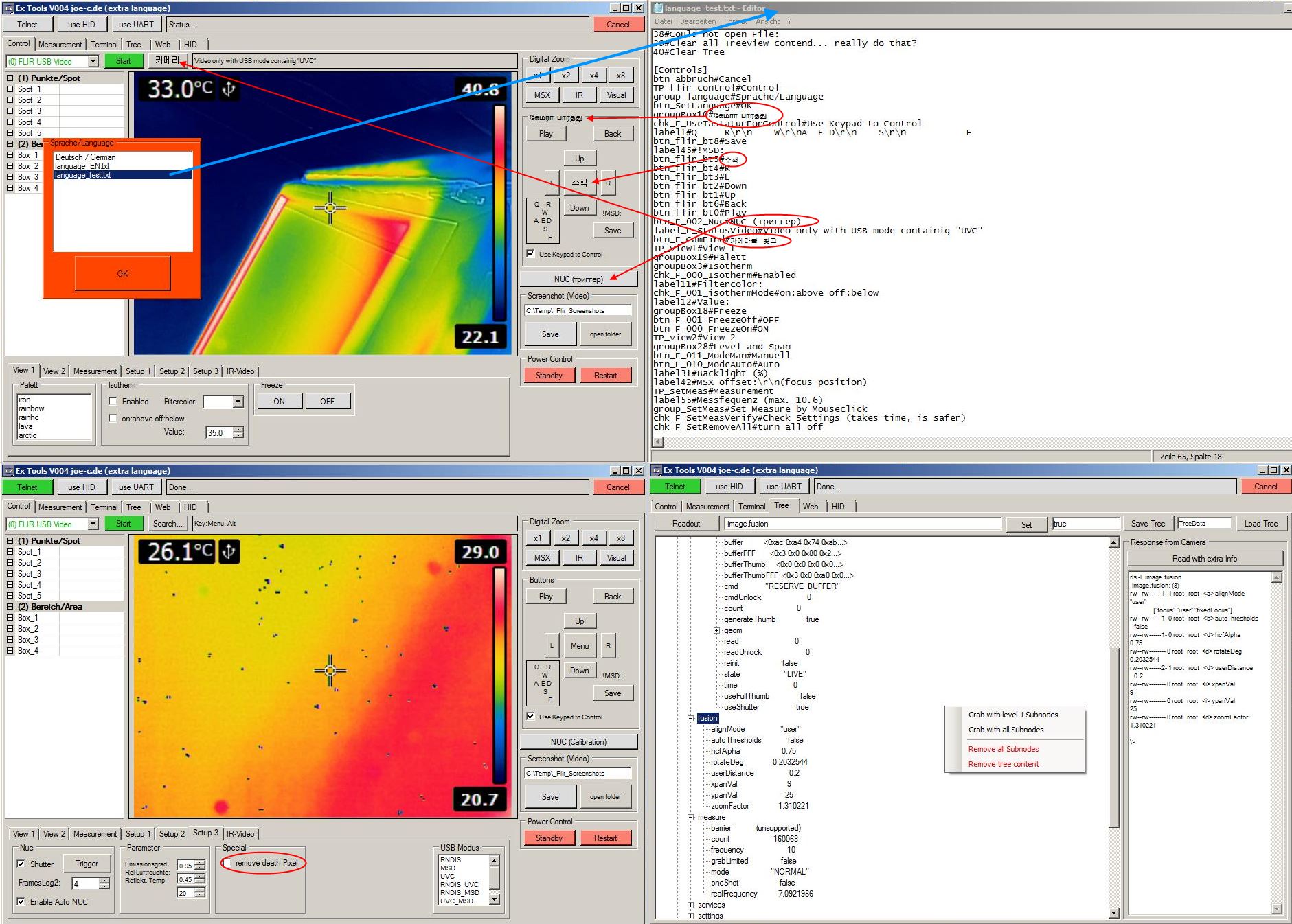
Bei dem ersten Start der Software sind 2 orange Fenster zu sehen:
Sprache/Language
Hier werden alle Sprachdateien aufgelistet. Wird eine Sprachdatei angewählt, werden die darin benannten Bedienelemente umbenannt. Man sieht nach einer Auswahl also sofort, was sie bewirkt.
Lizenz eingeben
Hier kommt der Lizenzcode rein, den ich per Email mit dem Programm zustelle. Ohne gültigen Lizenzcode sind die Verbindungsschaltflächen Telnet und UART abgeschaltet, so ist keinerlei Steuerung der Kamera möglich.
Die orange Lizenzbox verschwindet erst, wenn ein gültiger Lizenzcode eingegeben wurde. Der Lizenzcode wird in der "settings.txt" gespeichert. Wird sie von Hand gelöscht, muss man die Lizenz neu eingeben.
Ich empfehle für die Verwendung nur den RNDIS_UVC Mode. Damit kann man die Kamera optimal fernsteuern.
MSD (Festplatte) gibt einen zwar die Möglichkeit, die Kamerabilder direkt anzusehen und zu kopieren, aber dafür kann die Kamera während der USB Verbindung keine weiteren Bilder aufnehmen.
UVC (Webcam) zeigt das, was man auf dem Kameradisplay sieht auch auf dem PC mit 15 FPS.
RNDIS (Netzwerk) bietet einen Webserver, die Steuerungsmöglichkeit über Telnet und auch die Möglichkeit, über FTP die Kamerabilder runterzuladen. Man kann sogar im 2 Sek Takt das Kamerabild anzeigen lassen. Die von Hause aus nicht aktive RNDIS Funktion ist also die bei weitem vielseitigste. Braucht aber extra Treiber: flir_device_drivers.exe
die Kamera benutzt normalerweise die IP 192.168.0.2, aber eben nur, wenn diese IP nicht schon besetzt ist. Wenn sich die Kamera an ihrem Computer mit einer anderen IP anmeldet, können sie die im Tab:Web in der Textbox Telnet IP anpassen.
#Funktionen
Das Programm ist darauf eingestellt beim Starten nach Videoquellen zu suchen. Wenn eine gefunden wurde, die in ihrer Bezeichnung das Schlüsselwort "FLIR" zu stehen hat, wird sie automatisch gestartet.
Generelle Info zu den Steuerelementen:
Schaltflächen: drauf klicken und Funktion wird ausgeführt. Hellblaue Schaltflächen sind Makros. Die führen mehrere Einstellungen aus und brauchen daher länger.
Checkboxen: Häkchen setzen oder entfernen wird als Funktion an die Kamera gesendet.
Nummernfelder: wenn der Tastaturfocus auf der Nummerneingabe ist, kann sie mit Pfeil hoch und runter verstellt werden und wird mit ENTER an die Kamera gesendet. Direkteingabe der Werte ist natürlich auch möglich.
Wenn keine Verbindungsart gewählt wurde und eine Funktion benutzt wird, verbindet das Programm automatisch über Telnet. Es kommt vor, dass auf diese Weise die erste Steuerung fehlschlägt.
Ich empfehle nach dem Start erst mal einen Verbindungstest zu machen. Dafür nehme ich meistens die Farbpalette, da man hier schnell sieht, ob die Steuerung erfolgt.
#Darstellung 1
Auf dem ersten Tab "Steuerung" sind die meisten Steuerungsfunktionen zu finden.
Die leichten Direktfunktionen sind rechts, die komplexeren (oder nicht so oft benutzen) unten.
Tab: Darstellung 1
Palette
Hier kann mit einem Klick die Farbpalette geändert werden.
Isotherm
Hier werden alle Pixel mit Temperaturen ober/unterhalb eines Grenzwertes eingefärbt. Eingestellt werden kann zusätzlich die Filterfarbe (grau, rot, grün, blau, cyan, magenta, gelb) und die Darstellungsart (transparent, solid, linked). Mit "Alles einstellen" wird ein Makro aktiviert, das alle Einstellungen an die Kamera sendet.
Wenn "Einstellungsänderungen an die Kamera senden" aktiv ist, wird jede Änderung direkt an die Kamera übertragen. Die Option ist normalerweise abgeschaltet, weil sie sonst während des Einstellens für das Makro "Alles einstellen" stört.
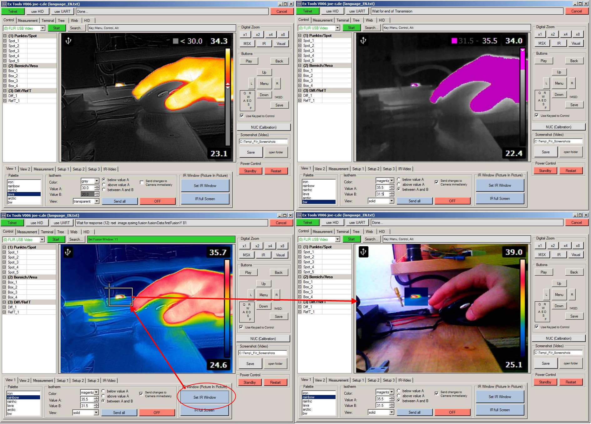
IR Fenster (Bild im Bild)
Zuerst ist zu erwähnen, BIB ist keine Funktion, sondern eine Einstellung. Wenn der IR Modus aktiviert wird ist das IR Bild über dem Visuellen Bild dargestellt. Beim BIB wird lediglich die Größe des IR Bildes anders eingestellt, der Darstellungsmodus ist der selbe.
Mit "IR Fenster festlegen" kann man ein Rechteck auf das Kamerabild zeichnen und so den IR Bereich festlegen. Mit "IR Vollbild einstellen" bekommt man wieder das reine IR Bild.
#Darstellung 2
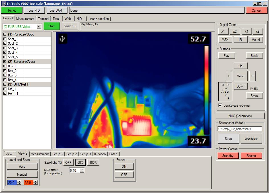
Tab: Darstellung 2
Level und Span
Hier kann die Autoskalierung auf "Manuell" gestellt werden. Damit lassen sich die Anfangs und Endtemperatur der Skalierung festlegen. Mit "Auto" erhält man den normalen Zustand der Kamera wieder.
Backlight %
Hier kann die Helligkeit der LCD Beleuchtung eingestellt werden.
MSX offset:
Hier kann man das einstellen, was man sonst im Menü unter "Focusposition" machen muss.
Diese Einstellung ist dafür verantwortlich, dass beim MSX die 2 Kamerasignale ordentlich übereinander liegen und auch beim BIB nicht verschoben sind.
Freeze
Frieret die Bilddarstellung ein (Standbild)
#Messung 1
Tab: Messung
Per Mausklick im Bild Einstellen
Die blauen Schaltflächen sind Checkboxen. Die Vordergrundfarbe zeigt den Aktivitätszustand der Messfunktion an (grün=aktiv, rot=OFF und schwarz=unbekannt). Wenn auf das Kamerabild mit der Maus geklickt wird, werden die unten aktiven (eingedrückten) Messfunktionen gesetzt. Messflächen werden wie ein Rechteck in Paint gezeichnet und ihre Werte werden alle nach und nach an die Kamera übertragen.
Das Häkchen bei "Einstellungen Prüfen" hat zur Folge, dass jeder Parameter (x, y...) nachdem er neu gesetzt wurde ausgelesen wird, um ihn mit dem zu setzenden Wert zu verglichen. Wenn es nicht passt, wird bis zu 3x neu gesetzt und ausgelesen. Das ganze führt zu einer erheblichen Verlängerung des Einstellvorgangs.
Dafür landen die Parameter aber auch wirklich in der Kamera. Andernfalls kann es passieren, dass die Kamera gerade zu beschäftigt ist (NUC...) um sich um den Befehl zu kümmern und daher einzelne Einstellungen nicht passen. Das passiert häufiger, je mehr Messungen aktiv sind.
Mit "alle Offline" werden alle Messungen abgeschaltet.
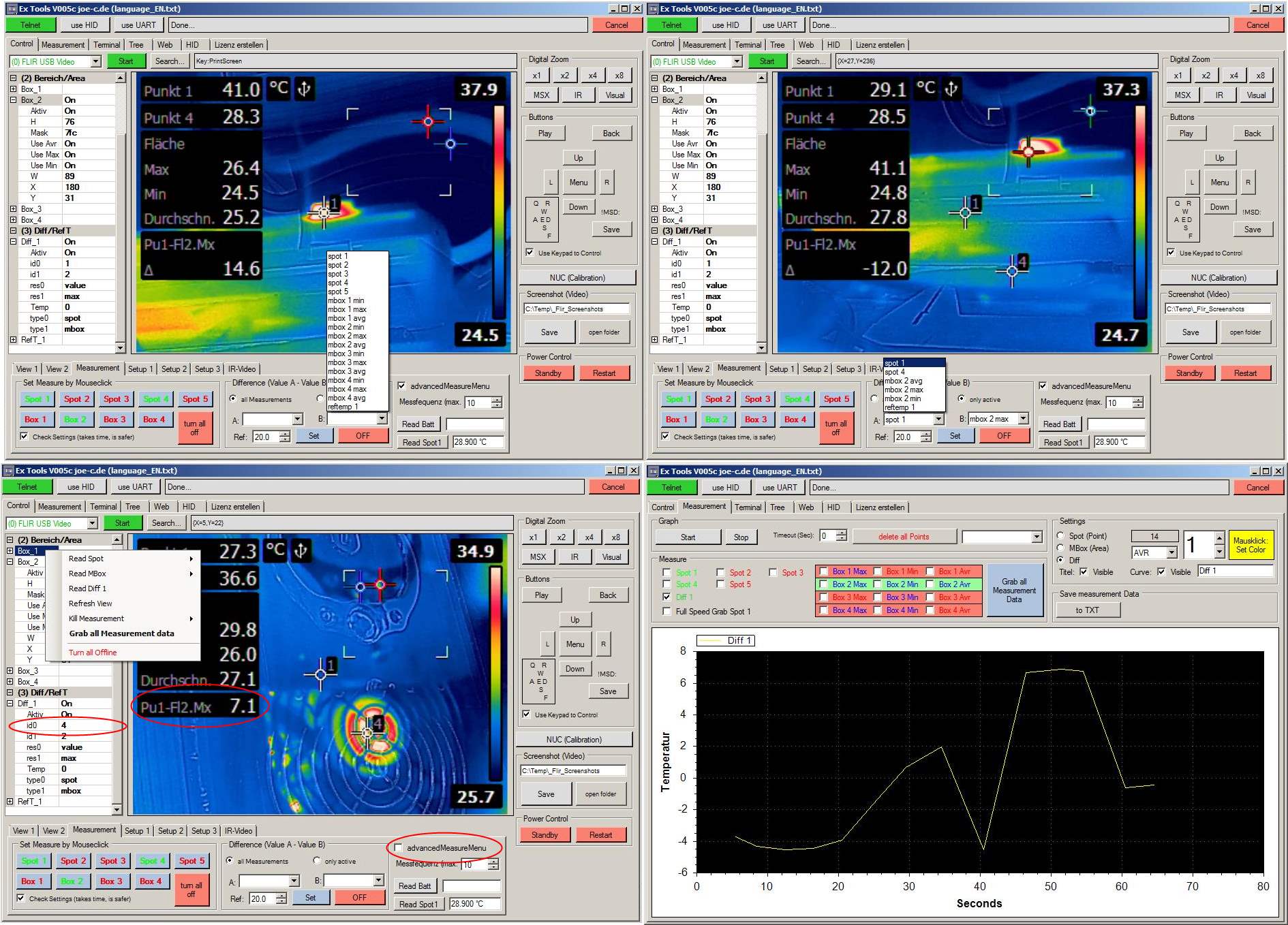
Differenz (Wert A - Wert B)
Sie können sich anzeigen lassen, wie groß die Differenz zwischen ihrem Messpunkt und dem größten/kleinsten Wert im ganzen Bild ist oder wie weit der größten/kleinsten Wert im ganzen Bild von einem eingestellten Referenzwert abweicht.
Es ist eine einfache Subtraktion. Der zweite eingestellte Wert (B) wird vom ersten Wert (A) subtrahiert und als Ergebnis angezeigt. Sowohl A als auch B können aktive Messungen, oder ein vorher eingestellter Referenzwert sein.
Der Referenzwert lässt sich auch direkt über die Nummerneingabe (mit ENTER) oder in der Messtabelle links vom Bild verstellen.
Der Differenzwert kann wie alle anderen Messwerte mit erfasst werden. Je mehr Messungen aktiv sind, desto geringer die Ausleserate... daher ist der Differenzwert nicht so oft auslesbar, wie ein einzelner Messpunkt.
Man kann alle Messwerte in der Auswahlliste haben, oder nur die aktiven. Aktive sind grün markierte in der "Per Mausklick im Bild einstellen" Box daneben. Um zu wissen welche aktiv sind, kann man entweder alle Messeinstellungen auslesen, oder auf den Kamerabildschirm schauen. Wenn RefTemp 1 als Einstellung genommen wird, werden zusätzliche Einstellungen vorgenommen und der bei Ref eingestellte Wert als Temperaturreferenz eingetragen.
Folgendes ist bei der Differenzmessung anzumerken:
- Wenn eine der eingestellten Messungen abgeschaltet wird, schaltet sich die Differenzmessung gleich mit ab.
Sie schaltet sich auch ab, wenn man eine Messung einstellt, die nicht aktiv ist. - Die Beschreibung in der Differenzanzeige (zeigt an, welcher Wert von welchem subtrahiert wird) ist abhängig vom "advancedMeasureMenu". Ist es eingeschaltet, funktioniert alles. Schaltet man das "advancedMeasureMenu" aber ab, ändert sich die Beschreibung nicht mehr. Der Wert wird richtig und neu berechnet, aber die Beschreibung beleibt wie sie war, oder ist ganz leer. (siehe Bild unten links...das Delta Symbol ist weg und Punkt 4 ist 7.1°C wärmer als der höchste Wert in Box2. Dennoch steht in der Beschreibung "Pu1" also Punkt 1)
Wenn bei einer aktiven Differnzmessung das "advancedMeasureMenu" abgeschaltet wird und man dann die Kamera neu startet, dann bekommt man nur einen schwarzen Balken mit dem Messwert.
Read Batt
Zeigt den Zustand der Kamerabatterie an. Einmal die Spannung in mV und die Ladung in %.
#Messung 2
Tab: Messung
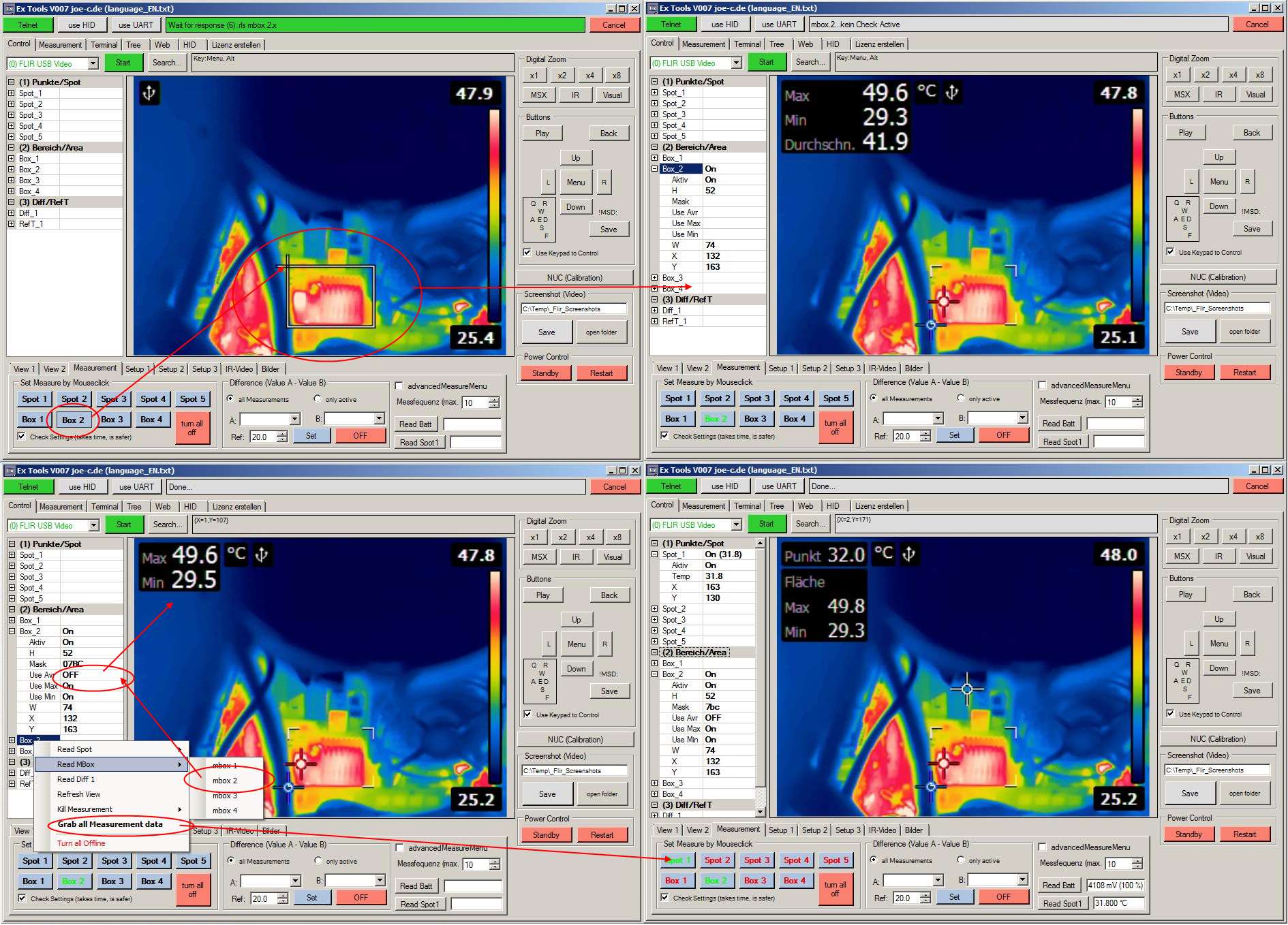
Hier kann man sehen, wie eine Messung per Software gesetzt wird (eine mbox in diesem Beispiel).
Zuerst wird die Messung im Tab angewählt, die gesetzt werden soll. Dann wird ein Rechteck auf das Livebild gezeichnet und gewartet, bis die Einstellungen an die Kamera übertragen wurden. Alle Einstellungen werden außerdem in die Messtabelle links neben dem Livebild gespeichert. Zusätzliche Einstellungen können über das Mausmenü (rechte Maustaste) ausgelesen werden. Dort können auch einfach die Messungen wieder abgeschaltet werden.
Wenn Einstellungen in der Tabelle geändert werden, wird das zur Kamera gesendet.
Die Messungen in der mbox werden über eine Calcualtion Mask (eine Variable, in denen einzelne Bits die Messungen einschalten) gesteuert. Wird eine der Messungen eingeschaltet, ohne vorher den Status auszulesen, werden alle anderen als inaktiv überschrieben.
Beispiel: man aktiviert von Hand mbox 3 und diese hat Min und Max eingeschaltet. Wenn man nun Max auf ein schaltet, wird die Variable für nur Max berechnet hat man danach nur Max aktiv.
#advancedMeasureMenu
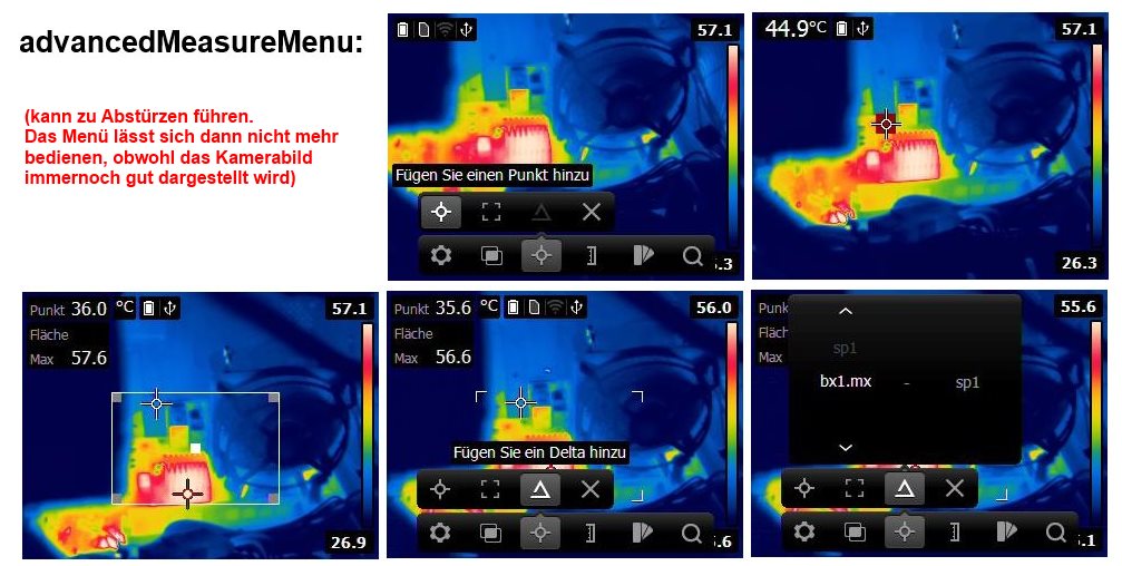
Wenn diese Funktion aktiv ist, können Messpunkte und andere Messfunktionen direkt von der Kamera aus eigestellt werden.
Allerdings hab ich mehrfach feststellen müssen, dass diese Funktion dazu führt, dass das die Menüsteuerung abschmiert. Von der Kamera kann dann das Menü nicht mehr benutzt werden, es bleibt in seinem Zustand, egal welche taste da gedrückt wird. Das gilt auch für die Fernsteuerung des Menüs.
Es gilt jedoch nicht für die generelle Fernsteuerung der Kamera.
Hier kann man immer noch ganz normal Messungen setzen, auslesen und Einstellungen verstellen.
Damit das Menü wieder richtig funktioniert, muss nur die Kamera neu gestartet werden. Möglicherweise gibt es auch einen Befehl die Menüapplikation wieder neu zu starten... hab aber noch nicht weiter danach gesucht.
Diese Option wird automatisch aktiviert, wenn die Differenzmessung genutzt wird, da ohne sie Darstellungsfehler auftreten.
#Setup 1-3
Hier ist der Bereich der erweiterten Einstellungen. Hier lassen sich Sachen einstellen, die ich nie bei anderen Kameras zu finden waren.
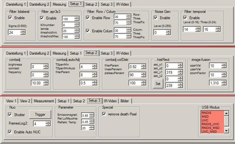
Setup 1:
Filter bilateral:
Ist sowas wie ein Weichzeichner... niedrig eingestellt ist es scharf und unsauber und hoch eingestellt wirkt es etwas Verschwommen.
Filter apr3x3:
Vermutlich ein Median Filter, noch nicht genauer erforscht...
Filter Row/Colum:
Ebenfalls noch nicht genauer erforscht. Es tauchen aber plötzlich ein paar Rauschlinien auf, wenn man sie abschaltet.
Noise Gen:
Der Noise Generator ist der Grund, warum bei der E4 die Thermal Sensitivity < 0.15°C ist. Hier wird der Sensor schlechter gemacht, als er ist...
Filter Temporal:
Wirkt wie Average und lässt ein sauberes und klares Bild entstehen... auf Kosten der Bildgeschwindigkeit.
Setup 2:
contadj / contadj.autoAdj / contadj.colDistr:
Diese Einstellungen verändern die Parameter der automatischen Einstellung für Level und Span. Hier kann den die Autoeinstellungen schnell oder langsam machen, die Schrittweite verstellen usw.
histRect:
Hier wird das Rechteck eingestellt, dessen Inhalt für Auto Level / Span benutzt wird. So kann man dafür sorgen, dass ein Rechteck im Zentrum für die Bildeinstellung des ganzen Bildes sorgt, genau so, wie es bei der PCE TC3 normalerweise ist.
.image.fusion:
Hier wird das Visuelle Kamerabild so verschoben und verstellt, das ihr Bild das IR-Bild sauber überlagert. Nur so hat man eine gute MSX-Darstellung.
Man könnte statt der Focusentfernung auch hier einfach x und y verstellen um sein MSX passend zu bekommen.
Es wäre sogar der Drehwinkel der Visuellen Kamera einstellbar, habs aber nicht extra eingebaut.
Hardware Anmerkung: man könnte (um die Lichtqualität zu verbessern), eine größere Linse vor die Kamera machen und die Einstellungen nachträglich so anpassen, das man wieder ein passendes MSX Bild bekommt.
Setup 3:
Nuc:
Bei der NUC (Non Uniformity Correction) wird ein Shutter vor den Kameradetektor geschoben, dessen Temperatur durch einen internen Temperatursensor bekannt ist. So wird der Temperaturdrift des Detektors ausgeglichen.
Hier kann man einstellen, wie viele Frames zum Abgleichen benutzt werden. Wenn der Shutter abgeschaltet wird, kann man ohne Shutter abgleichen. Egal was vorher zu sehen war, es ist dann unsichtbar. Hält man dann was vor die Linse, sieht es aus, als wäre das Bild "eingebrannt". Auf diese Weise kann man nicht vernünftig Messen... darum steht auch ein * vor den Messwerten. Aber man kann sehr gut Änderungen zum Vorzustand erkennen.
Das kann man z.B. verwenden, wenn man eine Platine betrachtet und nach dem Abgleich etwas ein oder ausschaltete und sich die Auswirkungen anschaut.
Parameter:
Zum verstellen der zur Temperaturmessung notwendigen Parameter.
USB Modus:
Hier kann eingestellt werden, wie sich die Kamera an das System anmeldet und welche Funktionen dann nutzbar sind.
Ich rate generell zu RNDIS_UVC.
MSD (Festplatte)
Hier sind die gespeicherten Bilder direkt abrufbar.
UVC (Webcam)
Kann von normalen Programmen als Videogerät geöffnet werden. Mit max. 15 FPS wird das, was auf dem Display zu sehen ist auch auf dem PC Dargestellt.
RNDIS (Netzwerk)
Die Kamera ist mit der IP 192.168.0.2 aufrufbar. Wird diese Adresse im Browser eingegeben, bekommt man ein Webinterface. Auch eine Webcam Seite ist aufrufbar http://192.168.0.2/webcam.asp, wo dann alle 5Sec das Kamerabild im Browser erscheint.
Außerdem wird er benötigt, um Datein von der Kamera zu Downloaden.
Das ist bei IR-Video notwendig, um an die Datei ran zu kommen
#IR-Video
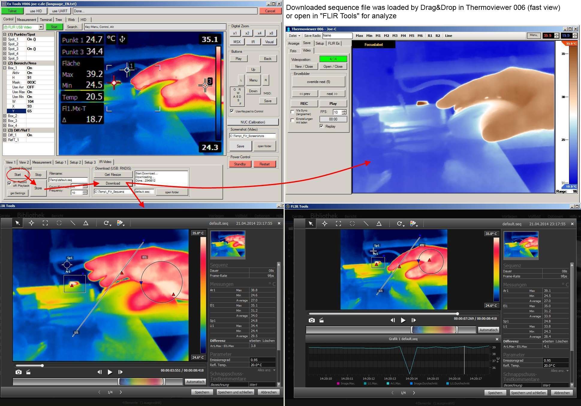
Die Kamera kann eine sogenannte Sequenz speichern, was im Grunde nix weiter ist, als aneinander geheftete Radiometrische Bilder in einer Datei. Wenn man die Bilder mit entsprechender Geschwindigkeit wiedergibt, hat man ein IR-Video.
Ich hab den Thermoviewer V006 entsprechend erweitert, ist aber derzeit noch nicht online gestellt. Dieser kann die Sequenz als relativ schnell öffnen und wiedergeben.
Die FLIR Tools können die Sequenz auch öffnen und man kann sie gut auswerten. Aber leider können die Frames (zumindest bei mir) nicht als Video dargestellt werden, weil es mehrere Sekunden dauert, bis das nächste Frame geöffnet ist. Sieht fast so aus, als würde hier FLIR mit seinem eigenen Format nicht richtig klarkommen.
Thermal Record:
Start:
Startet eine Aufnahme in den Zwischenspeicher. Stoppt automatisch wenn die Menge an Frames erreicht ist.
Stop:
Bricht eine laufende Aufnahme ab. Falls man es mal braucht...
Store:
Erstellt oder überschreibt eine Datei mit dem, was im Zwischenspeicher ist.
Play/Record:
Hier wird festgelegt, ob Start die Aufnahme oder Wiedergabe ausführt.
Filename:
Der Speicherpfad der Aufnahme.
Count:
Die Nummer der Gesamtbilder.
Frequency:
Die Geschwindigkeit der Bildaufahme. Max ist natürlich die Darstellungsfrequenz der Kamera.
get Settings:
Färbt die Einstellungen gelb (damit man weiß, wann die Abfrage fertig ist) und fragt die Zustände der Kamera ab. Sobald die Kamerawerte ausgelesen wurden, werden sie wieder weiß gefärbt.
Download:
(benutzt einen FTP Zugang zur Kamera, funktioniert daher nur mit USB: RNDIS, RNDIS_MSD und RNDIS_UVC)
Get Filesize:
Fragt ab, ob eine Datei existiert und wie groß sie ist. Der Dateiname ist der von Thermal Record->Filename.
Download:
Versucht die Datei runterzuladen. Wo die Datei hin soll und wie sie heißen soll stehen unterhalb der Schaltfläche. Vorhandene Dateien werden ohne Nachfrage überschrieben.
Ordner öffnen:
Öffnet den links eingestellten Ordner auf der Festplatte. Wenn der Ordner nicht existiert, wir er erstellt(ebenso bei Download)
Zusätzlich infos zum Thermal Record: es kommt vor, dass nach einer Aufnahme die Kamera plötzlich das Visuelle Bild darstellt.
Wird eine Sequenz auf der Kamera wiedergegeben, bleibt die Anzeige beim letzten Frame stehen. Die automatische Level / Span Anpassung läuft dann weiter mit dem was vor der Kamera ist. Angezeigt wird aber nur das letzte Bild von der Sequenz mit wechselnden Temperaturbereich. Wenn der NUC Abgleich ausgelöst wird, hat man wieder sein normales Kamerabild.
#Bilder
Tab: Bilder
Bilderordner von der Kamera (USB:RNDIS)
Ordner auflisten
Listet alle Ordner auf, die im DCIM Verzeichnis sind.
ausgewählten löschen
entfernt den rechts eingestellten Ordner.
Neu:
Erstellt einen neuen Ordner mit dem rechts daneben stehenden Namen.
Bilder von der Kamera auflisten
Erzeugt ein extra Fenster mit den Kamerabildern. Mehr dazu weiter unten.
Kamerabilder ab jetzt in diesem Ordner speichern
Legt den aktuell gewählten Ordner als Standardordner für die nächsten Bilder fest.
Bildzähler auf 0 (nächstes Bild: FLIR0001)
Setzt den internen Bildzähler auf 0 damit wieder bei 1 begonnen wird.
Interval (Zeitraffer)
(Funktioniert nicht im USB:MSD Modus)
Start
Timer starten, oder neu starten (reset).
Stop
Timer beenden.
H:MM:SS
Texteingabe der Laufzeit. Bei jeder Eingabe wird der Inhalt versucht auf die Zeitwerte (Stunden:Minuten:Sekunden) aufzuteilen. Wenn es nicht klappt, färbt sich das Feld. Nur wenn es weiß ist, kann der Timer gestartet werden.
Automatische Bildaufnahme in:
Zeigt die Zeit an, bis ein Bild aufgenommen wird. Zur Bildaufnahme wird das drücken der Store taste simuliert (die Taste ist unterhalb des Objektives). Ist grün, wenn es aktiv.
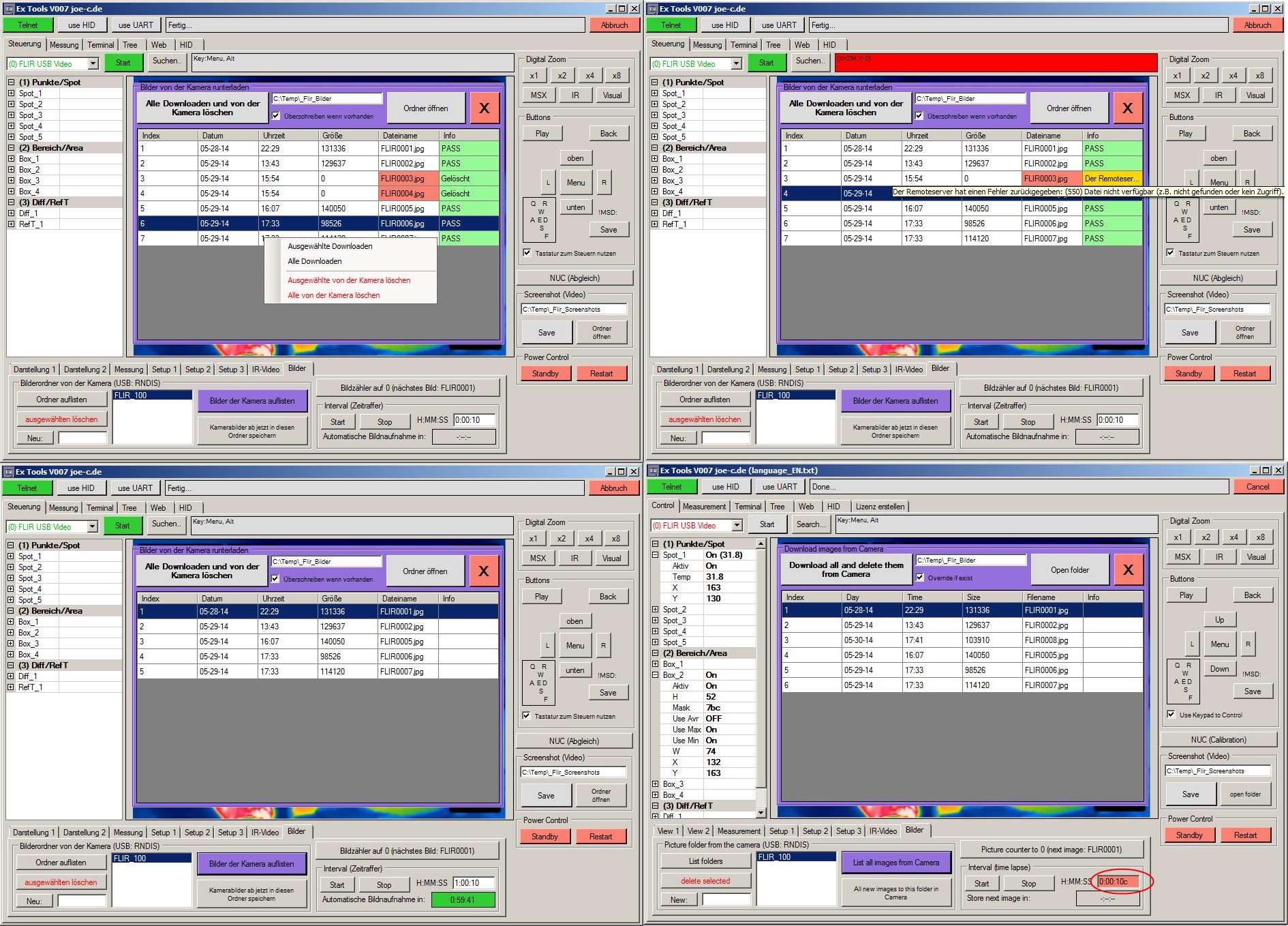
Extrafenster: Bilder von der Kamera runterladen
Alle Downloaden und von der Kamera löschen
Jede aufgelistete Datei wird zuerst runtergeladen. Das downloaden beinhaltet auch eine Prüfung der Dateigröße. Die Dateigröße wird mit FTP ausgelesen und nach dem Download mit der erstellten Datei verglichen.
Wurde die Datei runtergeladen wird sie von der Kamera gelöscht. Dann geht es mit der nächsten Datei weiter.
Am Ende sind keine Bilder im Kameraorder sondern alle in dem rechts eingestellten lokalen Bilderordner.
Überschreiben wenn vorhanden
Wenn aktiv, wird eine bereits runtergeladene Datei erneut runtergeladen.
Wenn abgeschaltet, wird eine bereits vorhandene Datei beim runterladen umbenannt (FLIR0003 -> 1_FLIR0003 ... 2_FLIR0003 usw.)
Ordner öffnen
Öffnet den eingestellten Ordner und erstellt ihn wenn nötig.
X
Schließt das extra Fenster. Mit der ESCAPE Taste wird das Fenster auch entfernt.
Bei der Tabellenauflistung gibt es auch ein Mausmenü (mit rechtsklick). Hier können gewählte oder alle gedownloadet oder gelöscht werden.
#Tab: Messung
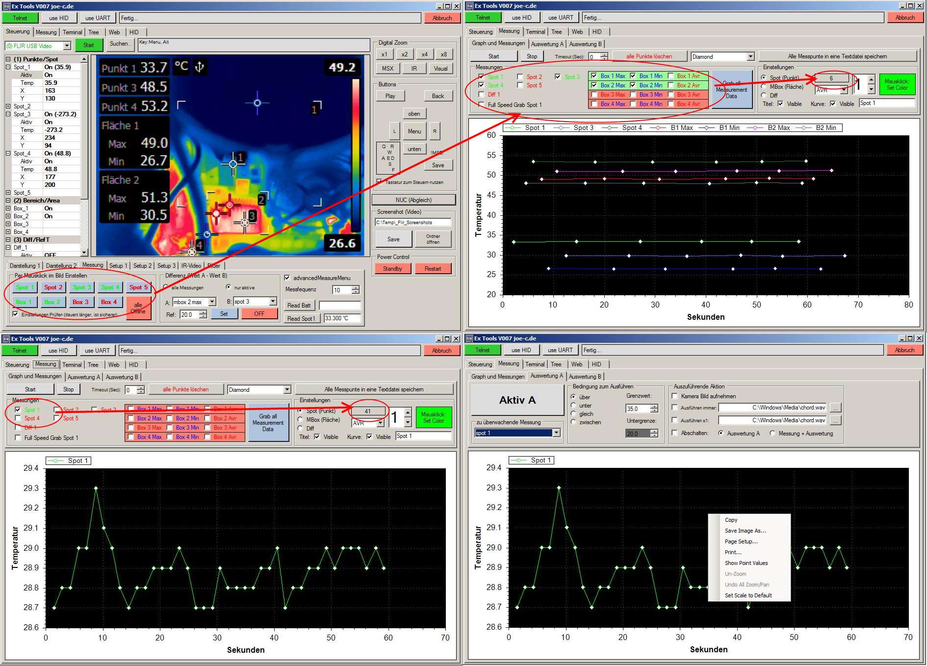
Hier werden Messwerte von der Kamera erfasst. Die Messwerte kommen genauso von der Kamera... es werden keine Rohdaten ausgelesen und umgerechnet (davon abgesehen, dass die Kamera ihre Werte manchmal in Kelvin liefert). Je mehr Messpunkte aktiv sind, desto beschäftigter ist die Kamera und umso seltener bekommt man Messwerte.
Wenn viele Messungen aktiv sind, sollte der Timeout (Tab: Terminal) höher gestellt werden. Sonst meldet sich der Timeout bevor der Messwert ankommen konnte.
Die Messwerte ändern sich natürlich nur, wenn die Messung auch aktiv ist. Wenn nur eine Messart aktiv ist, wird sie nicht nummeriert. Ist nur Punkt 1 aktiv oder nur Punkt 3, dann sieht es beides gleich aus. Wenn die Punkte per Software gesetzt oder abgeschaltet werden, sind sie Farblich markiert. Grün ist aktiv, rot ist inaktiv.
Der Status kann mit "Grab all Measurement Data" aktualisiert werden.
Der Datenempfang läuft seriell und Asynchron ab. Es wird nach Messwert x gefragt und wenn die Antwort kommt, dann wird sie mit entsprechender Uhrzeit versehen. Die Uhrzeit in Sec zeigt also an, wann die Messungen eingetroffen ist, nicht wann nach ihr gefragt wurde.
Graph:
Start:
Startet einen Timer, der die Messungen ausliest.
Stop:
Hält den Timer bei der nächsten Gelegenheit an.
Timeout:
Legt fest wie viele Sekunden nach einem Durchlauf gewartet wird, bis der nächste beginnt.
Alles Löschen:
Löscht alle Messpunkte von allen Messungen.
Symbolauswahl (rechts neben Alles Löschen):
Legt fest, mit welchem Symbol die Messpunkte dargestellt werden sollen. Standard ist ohne Symbol (none).
Messungen:
Grab all Measurement Data:
Durchläuft in einer Abfrageschleife alle Messungen und Messflächen und stellt den Zustand bei den Auswahlfeldern dar. Da es 10 Abfragen sind (Verbindungstest+5xMesspunkt+4xMessfläche) dauert das ganze etwas.
Spot x / Box x Max-Min-Avr:
Die zu abfragende Messung.
Der Messtyp mbox hat 2 aktivierungszustände. Zum einen wird die aktivierte Messung (Min, Max, Avr) in eingeschalteten zustand blau angezeigt. Aber eine eingeschaltete Messfunktion kann nicht ausgelesen werden, wenn die box nicht aktiv ist. Daher ist hinter den 3 Messfunktionen ein farbiges Feld, dass den Zustand der mbox selbst zeigt (helles grün=aktiv, helles rot=OFF und grau=unbekannt).
Einstellungen:
Hier können Darstellungseinstellungen gemacht werden für einzelne Messungen.
Farbe der Messkurve, Bezeichnung im Titel...
Wenn eine Messung ausgewählt wird, werden ihre Zustände zum verstellen aktualisiert (Farbe der Linie, Sichtbarkeit des Titels, Name des Titels...). Oberhalb der Combobox (min, max, avr) wird angezeigt, wie viele Messpunkte bisher gesammelt wurden bei der gewählten Messlinie. Die Anzahl der Punkte kann bei mehreren Messungen unterschiedlich sein.
Alle Messpunkte in eine Textdatei speichern:
Speichert alle vorhanden Messungen in eine Textdatei. Da der Datenempfang asynchron ist, wird jede Messkurve einzeln ausgegeben. Außerdem kann es vorkommen, dass die Messungen unterschiedliche Gesamtmesspunkte haben.
Zum Graphen selbst.
Mit der linken Maustaste kann die Messkurve verschoben werden.
Mit der mittleren Maustaste kann man ein Rechteck zeihen, dass dann groß dargestellt wird (Zoomfunktion).
Mit der rechten Maustaste erscheint ein englisches Mausmenü mit diversen Funktionen, wie dem abspeichern des Graphen als Bild.
Tab:Analyse A/B
Hier wird eine erweiterte "wenn... dann..." Funktion basierend auf den Messungen zur Verfügung gestellt.
Aktiv A/B
Schaltetet die Analyse ein.
Zu überwachende Messung
Hier wird eine der Messungen gewählt, die im Graphen gemessen werden (der Inhalt der Auswahl wird immer aktualisiert, wenn das Tab Analyse angewählt wird und die Analyse gerade nicht aktiv ist)
Bedingung zum Ausführen
Hier wird eingestellt, bei welchem Bezug zur Messung und bei welchem Grenzwert eine Bedingung als erfüllt gelten soll.
Auszuführende Aktion
Hier wird festgelegt, was passieren soll, wenn eine Bedingung als erfüllt erkannt wurde.
- Kamera Bild aufnehmen
bedeutet, dass ein Druck auf die Speichertaste der Kamera simuliert wird (genauso wie beim Zeitraffer) - Ausführen immer
führt die dort eingestellte Datei jedes Mal aus, wenn die Bedingung erfüllt wird. Die eingestellte Datei kann fast jede sein, die sie auf ihrem System haben. Es wird dann ein Bild angezeigt oder ein Video abgespielt, oder (wie voreingestellt) eine Sounddatei wiedergegeben... man kann auch ein anderes Programm starten oder was auch immer. - Ausführen x1
Startet eine Datei und schaltete sich danach selbst ab. Es wird also einmal beim Erreichen der Bedingung ausgeführt und dann nicht mehr, egal wie oft die Bedingung wieder erfüllt wird... es sei denn, man schaltete sie von Hand wieder ein. - Abschalten
schaltet entweder nur die Analyse oder gleich die ganze Messerfassung.
#Tab: Terminal
Das Terminal ist das einzige, was von der Vorlage DevTools noch geblieben ist. Aber auch hier wurde einiges angepasst.
Steuerungselemente:
Save:
Speichert den Inhalt der beiden Textfelder (links ASCII, rechts Bytes ) in separate Textdatein.
Clear:
Löscht beide Textfelder.
Flirresponse mit...:
Gibt auch Datenkommunikation außerhalb des Terminals aus.
Open last:
Öffnet direkt den eingestellten COM Port. Dieser wird auch in der Settings.txt bei schließen gespeichert und beim starten wieder geladen.
Das wurde eingebaut, weil Bluetooth COM-Ports länger zum öffnen brauchen (Pairing) und es daher Sinn macht, sie schon voreinzustellen.
Timeouts:
Hier kann die Timeoutzeit in Sek. eingestellt werden. Das muss man im einsatz höher stellen, wenn sehr viele Messungen aktiv sind, da sich dann auch das Antwortverhalten der Kamera verlangsamt.
Open:
Öffnet den darunter eingestellten COM-Port. Schlägt das Öffnen fehl, wird automatisch nach COM-Ports gesucht.
Refresh Ports:
Versucht von COM1 bis COM99 die Ports zu öffnen. Jeder Erfolg landet in der Auswahlbox unterhalb von "Open".
Open:
Ober und unterhalb kann die Übertragungsgeschwindigkeit eingestellt werden. Das ist nur bei einer Direktverbindung wichtig, bei Bluetooh ist sie egal, da das von der Hardware geregelt wird.
Textfeld Bytes:
Sendet die eingestellten Bytes... ist inzwischen eigentlich überflüssig.
Textfeld Text:
Sendet das dort eingestellte an die Kamera.
Textfeld Rset:
Sendet "rset " + das dort eingestellte an die Kamera. Ist zum verstellen am Resource Tree.
Textfeld Rls:
Sendet "rls " + das dort eingestellte an die Kamera. Ist zum auslesen vom Resource Tree.
#Tab: Tree
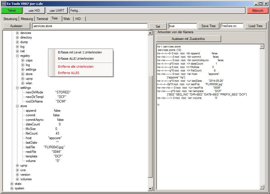
Hier kann der Resource Tree erforscht werden. Der Resource Tree ist verfügbar, wenn die Kamer eingeschaltet ist (anders als bei Befehlen wie "ver" oder "restart", die auch bei einer Kamera im Standby funktionieren).
Dort lässt sich verdammt viel an der Kamera verstellen, bei weitem mehr als in irgendeinem Kameramenü.
Linke Maustaste: Knoten auswählen und Unterknoten ein/ausklappen. Das gewählte Objekt wird neben Auslesen mit dem vollen Pfad reingeschrieben.
Mittlere Maustaste: führt Auslesen aus.
Rechte Maustaste: Mausmenü mit weiteren Funktionen:
(Der aktuell bearbeitete knoten steht neben Auslesen und gilt als Basis für die Anfrage.)
- Erfasse mit Level 1 Unterknoten
- Erfasse ALLE Unterknoten
- Entferne alle Unterknoten
- Entferne ALLES
Auslesen:
Fragt die Kamera nach dem Inhalt der rechts daneben eingestellten Resource Node. Was von der Kamera empfangen wurde, wird in die Tree-Anzeige mit eingefügt.
Anmerkung: Die Kamera gibt, wenn ein Resourceknoten angefragt wird, immer die Unterknoten mit aus, diese werden entsprechend aufbereitet und eingefügt. Wenn es zu einem Lesefehler kommt, steht dann aber leider auch Schrott im Tree-View. Bei jedem neu auslesen, wird das Alte raus gelöscht. Man kann also mehrfach auslesen und wenn das gleiche da steht, dann sollte es auch passen.
Steht neben dem Knotennamen ein Wert, so ist dies das Knotenende. Der Wert kann mit Set verändert werden.
Wird ein Knotenende ausgelesen landet es parallel zum Knoten in der Liste. Gut zum vergleichen, versaut aber den Baum an der Stelle. Der Überknoten sollte nach so einem Vorgang also nochmal ausgelesen werden, damit da kein Mist drin steht.
Set:
Sendet den rechts daneben stehenden Wert zur Kamera. Alternativ kann bei der Textbox auch ENTER benutzt werden. So kann man relativ einfach die Einstellungen im Resource Tree verändern.
Save Tree:
Speichert alle in der Anzeige vorhandenen Resourcen in eine Textdatei.
Load Tree:
Liest die Textdatei aus und stellt es wieder als Baum dar.
Auslesen mit Zusatzinfos:
Liest den eingestellten Treenode (rechts neben Auslesen) mit der Option "-l" aus, was zusätzliche Informationen gibt wie z.B. den einstellbaren Bereich einzelner Werte.
Der vollständige Baum meiner Kamera wird mitgeliefert. Man kann also gleich den Baum meiner Kamera laden, sich durchschalten zu dem für sie interessanten Bereich und ihn mit Werten aus ihrer Kamera überschreiben lassen.
Beispiel: sie wollen wissen, unter welcher Nummer das nächste Bild gespeichert werden wird. Die direkte Knotenpfad lautet ".services.store.nextFile". Also muss man ".services.store" anwählen und Auslesen. Und schon hat man alle Unterknoten von "store" mit den aktuellen Werten der Kamera.
Unter "nextFile" wird die nächste Nummer benannt.
Wird "fileCount" angewählt und man gibt neben Set den Wert "10" ein, dann wird als nächstes die Nummer "0011" gespeichert werden.
#Tab: Web
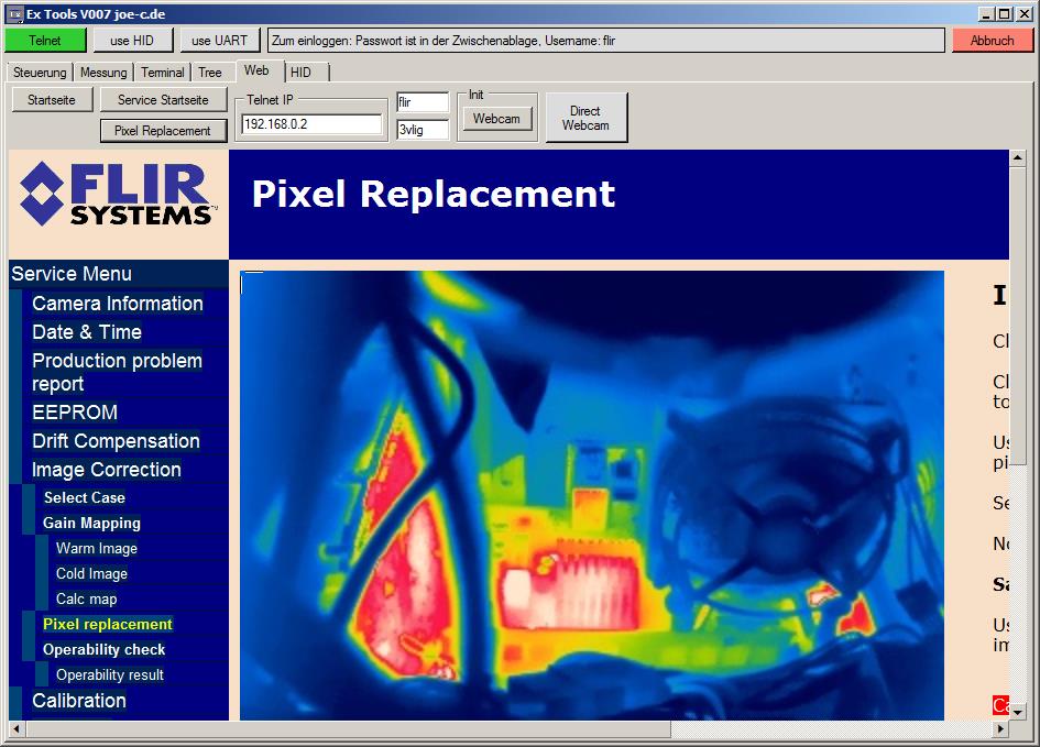
Hier ist ein rudimentärer Webbrowser eingebaut. Allerdings eher zum testen...
Auf diesem Tab kann auch die Telnet IP verstellt werden, wenn ihre Kamera eine andere verwendet.
Mit Init:Webcam wird die Seite http://192.168.0.2/webcam.asp aufgerufen. Auf dieser Seite wird das Kamerabild alle 5 Sek aktualisiert.
Die Funktion Direct Webcam liest das Bild ungefär im Sekundentakt aus.
Das erfassen eines Bildschirmfotos läuft wie folgt:
- Befehl "rset .image.services.store.commit true" senden. Dadurch speichert die Kamera das aktuelle Bildschirmbild in eine Datei.
- Bild http://192.168.0.2/Ram/web.jpg auslesen.
Dann geht es wieder mit dem Befehl weiter...
Jedenfalls könnte man sich eine Webseite erstellen und auf die Kamera packen, mit der die Kamera komplett über eine Webinterface gesteuert werden könnte
#Version 008
Neben der Beseitigung kleinerer Fehler betrifft die neue Version vor allem die Live Videoanzeige.
Tab:Movie
Es gibt nun die Möglichkeit ein Video (.avi) von der Livebildanzeige aufzunehmen.
Videocodec
Hier werden die auf ihrem System verfügbaren Videocodecs aufgelistet. Ich hatte bisher die besten Ergebnisse (Größe / Qualität) mit dem "msvc" codec, weshalb dieser voreingestellt wird, wenn vorhanden.
Videopfad und Dateiname
Pfad und Dateiname halt. Die Videoendung kann bei anderen codecs entsprechend anders sein und muss von Hand angepasst werden.
Erstellen
Erstellt die unten angeben Datei zum beschreiben. Ist sie schon da, wird gefragt, ob sie überschrieben werden soll. Die Videodatei hat immer 320x240 bei 15FPS.
Speichern und schließen
Speichert alle Frames usw. in die Datei und schließt sie. Das Video ist dann fertig zum betrachten.
Ordner öffnen
Öffnet den eingestellten Videoordner.
Aufnahme
REC
Wenn aktiv, wird Rec in roter Hintergrundfarbe dargestellt und alle Frames, die angezeigt werden landen parallel auch in der Videodatei.
Einzelbild einfügen
Hierbei wird nur ein Frame in die Videodatei eingefügt. So kann man eine Serie von Einzelbildern als Video abspeichern.
Positionsanzeige (unterhalb des Labels "MM:SS (Bilder)")
In der Positionsanzeige ist die bisher aufgenommene Zeit und in Klammern die Einzelbilder insgesamt zu sehen.
Interval (Zeitraffer)
Funktioniert genau wie im Tab:Bilder, nur dass nach Ablauf der Zeit kein Kamerabild aufgenommen wird sondern ein Videobild in die Videodatei.
Der Intervall ist also ein einstellbares automatisches klicken auf "Einzelbild einfügen".
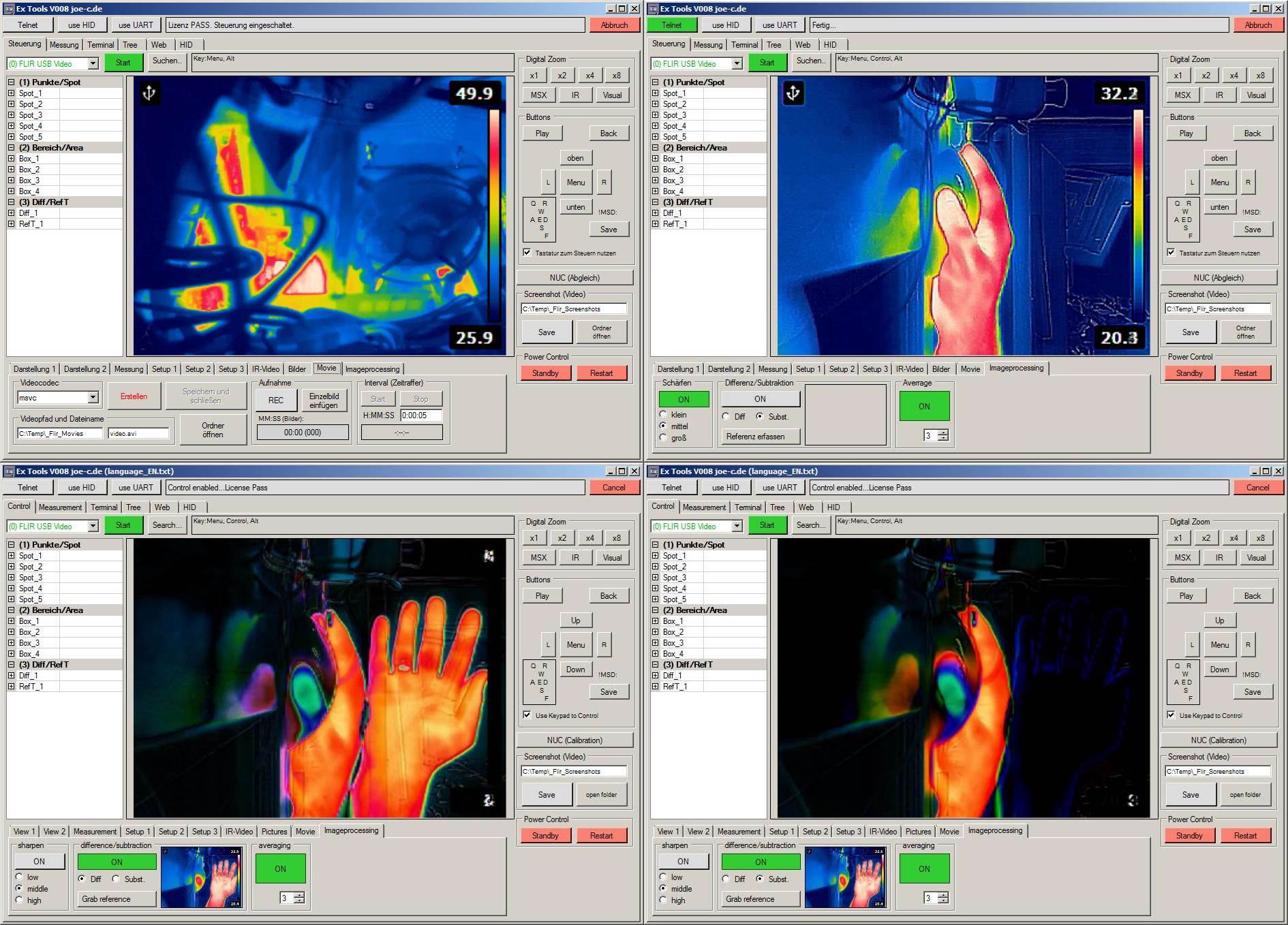
Tab:Imageprocessing
Hier sind Videofilter für die Livebildanzeige einstellbar.
Schärfen (klein, mittel, groß)
Erzeugt stärkere Kantenübergänge und so ein schärfer wirkendes Bild.
Differenz/Subtraktion
Ein aktuelles Kamerabild wird als Referenz erfasst (also im Hintergrund gespeichert).
Dieses Refernezbild wird entweder vom aktuellen Kamerabild subtrahiert, oder es wird eine Differenz gebildet. Die Unterschiedlichen Auswirkungen sind im Screenshot zu sehen.
On
schaltet die Funktion ein.
Diff
Erzeugt ein Differenzbild von Hintergrundbild zu aktuellem.
Subst.
Erzeugt ein Subtraktionsbild von Hintergrundbild - aktuellem.
Referenz erfassen
Das aktuelle Kamerabild wird als Hintergrundbild gespeichert.
Averrage
Die eingestellte Anzahl an Bildern wird gemittelt. Die Voreinstellung ist 3, also besteht jedes aktuell betrachtete Bild aus der Mischung mit den 2 vor ihm. Bei den 15PFS der Bildanzeige reicht es aus, um Änderungen zu sehen aber gleichzeitig ein rauscharmes Bild zu haben.
#Version 009
Die Oberfläche wurde optisch angepasst, weg vom normalen Windowsfensterstyle. Des weiteren wurden auch neue Funktionen eingebaut.
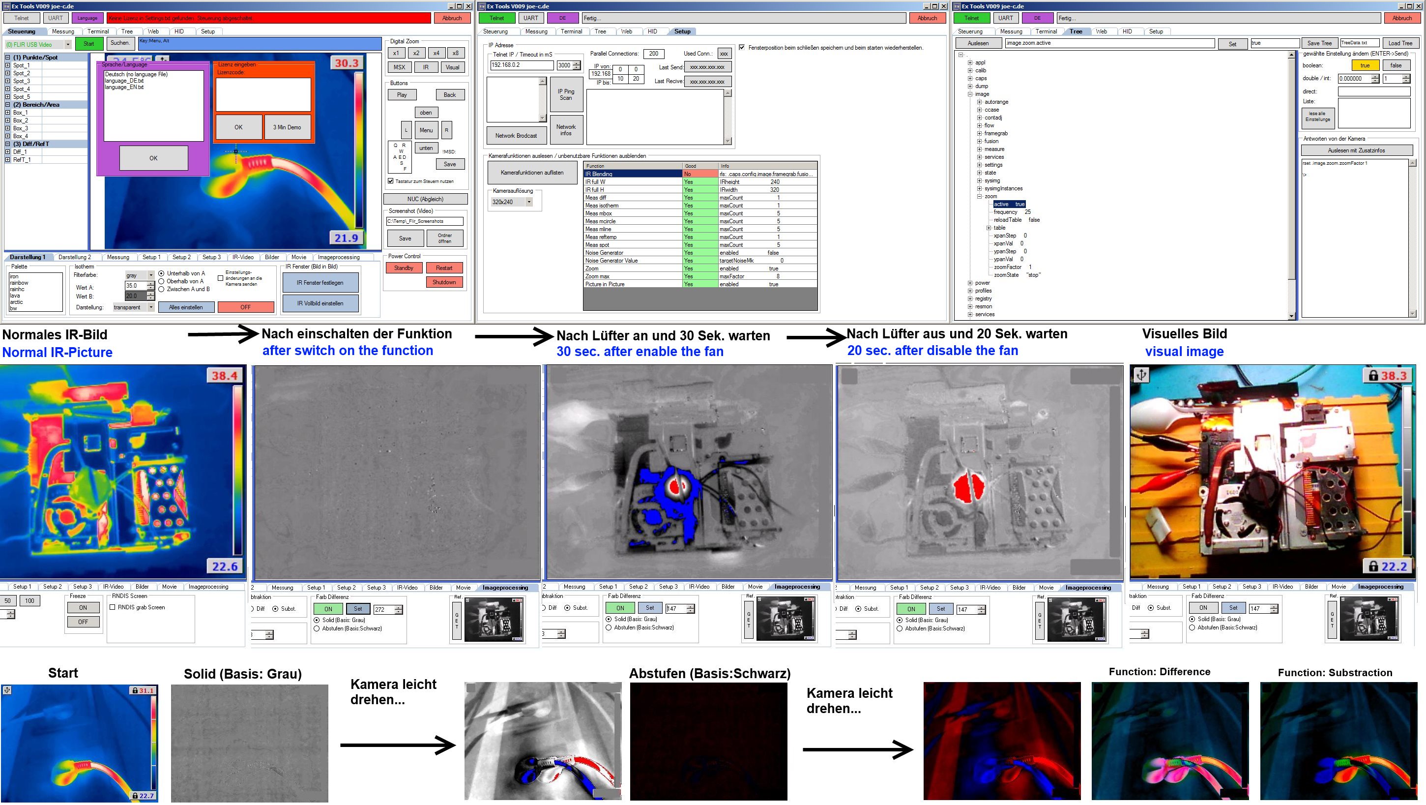
3 Min Demo
Ohne die Kameraverbindung, gibt es kein Zeitlimit für das Erkunden des Programms.
Sobald der Demomodus aktiv ist, kann eine Verbindung zur Kamera hergestellt werden und das Programm lässt sich 3 Min lang ohne Einschränkung nutzen. Die Zeit zählt erst, wenn die Verbindung erfolgreich zur Kamera hergestellt wurde. Im Anschluss schließt sich das Programm automatisch.
IP Scanner
Ein neues Feature, was das suchen und finden der Kamera vereinfachen soll.
Kamerafunktionen und Auflösung
Damit beim setzen der Messpunkte auf dem Bildschirm die Abmessungen passen, wurde eine Auflösungsauswahl eingefügt. Hier ist die Auflösung der Kamera (bzw. der Anzeige) auszuwählen. Getestet wurden bisher die FLIR Kameras (E4, E8, C2, I3, I7).
Zeitanzeige beim Messgraph
Früher wurden die vergangenen Sekunden seit Messungsstart gezählt. Jetzt sind 2 Zeitangaben verfügbar. Beispiel mit 15Sec Messung:
- Zeit seit Messbeginn liefert eine relative Zeitangabe (00:00:00 bis 00:00:15)
- Systemzeit liefert eine absolute Zeitangabe (13:34:11 bis 13:34:26)
Farb Differenzmessung
Beim Initialisieren wird die Kamera auf einen festen Temperaturbereich eingestellt (aktuell angezeigte Temperaturen).
Dann wird die Palette auf Graustufe umgestellt und das Kamerabild als Referenzbild genommen.
Alles was ab jetzt wärmer wird, wird heller und ab der Schaltschwelle ROT.
Je kälter desto dunkler und ab der Schaltschwelle BLAU.
Alternativ kann die Basis von Grau auf schwarz gestellt werden... dann wird:
Je wärmer desto intensiver ROT und je kälter desto intensiver BLAU.
Wenn zu erwarten ist, dass die Temperaturen den oberen oder unteren Temperaturbereich übersteigen, kann man eine manuelle Anpassung nehmen und das Referenzbild mit "GET" überschreiben.
#Download
rel ex tools v010 (ZIP, 1.48 MB)
Ab jetzt ohne Lizenzbeschränkung zum Download.
Rescan: 15.10.23 -> 1/64
Rel_Ex-Tools_V011.zip (1.7 MB)
Die Scans vom 27.4.17 zeigen leider Falscherkennungen beim Virenscan (Gescannt mit: Virustotal)
Scan: Rel_Ex-Tools_V011.zip (1/58)
Rescan: 15.10.23 -> 3/64
Projektänderung
Inzwischen ist dieses Programm umbenannt worden in: "Camera Commander: FLIR"
und seit Version 1.9.0.0 ist sie fester Bestandteil der ThermoVision_JoeC Software.
Zuletzt geändert am: Apr 27 2017 um 8:41 PM